|
|||||||||||||||||
|
Building the Baldwin Reservoir, Cleveland Water-Works Mixing Plant Has Duplicated Equipment--Cableway Electrically Operated and Synchronized--Seven-Yard Concrete Bucket and Sixteen-Ton Ships A covered reservoir of reinforced concrete having the remarkable lateral dimensions of 1,035 x 551 ft. and a height of 39 ft. is nearing completion for the water-works of Cleveland, Ohio. The area and height and the volume of concrete, 104,100 cu.yd., make this perhaps the largest covered reservoir in America. Because of these large dimensions, the thick and high columns and the unusual spans of the groined arches of the roof, the construction task has been correspondingly unusual and the contractor has developed a highly improved plant for his operations. In particular he has demonstrated that the mobility of the cableway reaches considerably beyond the limits that are ordinarily assigned to it as a construction tool.
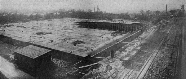
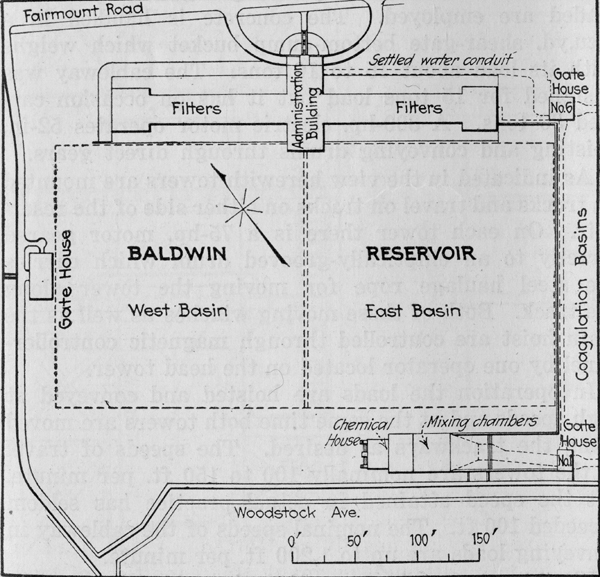
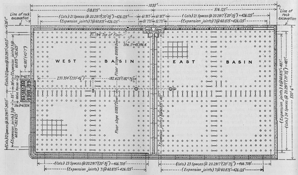
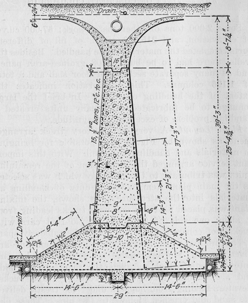
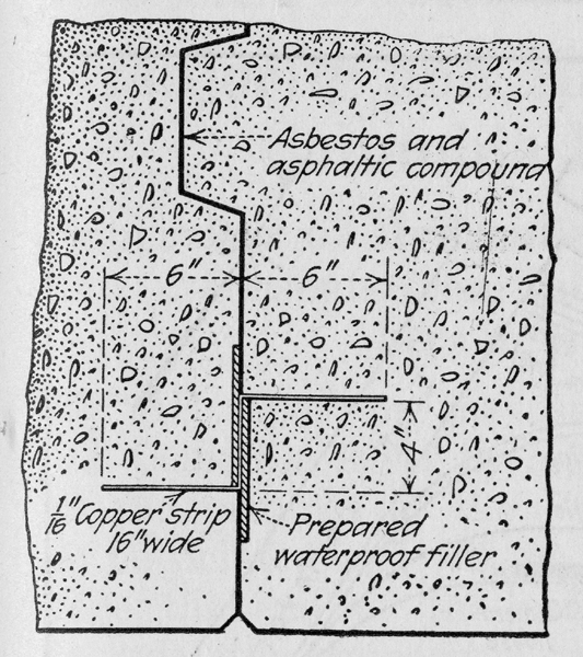
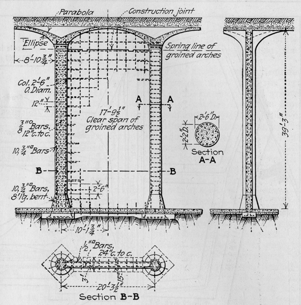
Each half of the reservoir requires a roof approximately 500 ft. square consisting of 1,104 groined arch panels 20 ft. square on columns nearly 35 ft. high The new reservoir for Cleveland is known as the Baldwin Reservoir and is a part of the new filtration works located just east of the old Fairmount reservoir. In fact the Fairmount reservoir, with its two basins of 80,448,400 gal. combined capacity, will be the receiving basin for the new filtration works. These comprise a chemical house, mixing flumes, coagulation basins and a clear water reservoir, which is the Baldwin reservoir that is being described. The diagram plan, Fig. 2, shows the relative locations of the several units. With mention that the Baldwin reservoir was planned, and indeed partly excavated, as a storage reservoir and its dimensions were not changed when it was made a unit of the new filter plant, further reference to its functions as a part of this development may be omitted. Structurally, and also as a construction problem, the governing factor of the new reservoir is its size. The large lateral dimensions give an enormous roof area and the depth of the basin gives a great height of column. The views, Fig. 1 showing the roof area of half the reservoir, the smallest unit embraced by walls, and, Fig. 3 showing the forest of columns, nearly 35 ft. in clear height, vision the situation fairly well. Actual lateral dimensions are given by the plan, Fig. 4. Substantially there are between walls two 500-ft. squares of roof each consisting of 1,104 groined-arch panels supported by 1,196 columns, 30 in. in diameter and 34 ľ ft. high from footing level to the springing line of the arches. General Structural Design--A brief explanation of the main operating functions of the reservoir helps in understanding the structural elements. Water from the filters enters a flume hung to the north wall of the reservoir 21 ft. above the floor. Wier notches in the front wall of the flume deliver the water into the two basins across which it flows and enters two conduits, one from each basin, leading to the gate house where an elaborate set of valves turns it into the distribution system. One of the outflow conduits is a box-structure in the angle of the south wall and the floor, and the other is within the wall, with its bottom at floor level. Admission to both conduits is through a row of orifices so proportioned that the rate of admission is uniform the whole length of the conduits. In the same manner the flow into the reservoir from the flume is kept at a uniform rate throughout its length. Briefly, careful thought has been given in designing both inlets and outlets to ensure an even, steady current in the reservoir water and thus eliminate surging and stagnant corners. Wall design was modified to some extent by the requirements for interior conduits and by the fact that the excavation made originally, required the wall to be thickened at places, but generally the outside walls are of the ordinary abutment-wall type. A section of the division wall between basins is shown by Fig. 5. It is a sturdy section heavily reinforced for full head on one side only, although normally this condition of loading will not exist. The design calls for the construction of the walls in two lifts, with keyed construction joints, and for vertical expansion joints about 60 ft. apart. The vertical joints are keyed and have the copper-strip water-stop arrangement shown in Fig. 6. As the reservoir is founded on shale rock the floor design called for a sub-floor, to level up the rock bottom, and a 9-in. plain concrete slab with joints dividing it into squares corresponding to the panel between four columns and also with joints between it and the column base. Nominally the sub-floor was 3 in. thick, but due to the rough breaking of the shale ledge it averaged perhaps more nearly a foot thick. The floor has a very slight fall, 1˝ ft., from each wall toward the middle as indicated in Fig. 4. The outstanding feature of the floor design is that it is not only divided by expansion joints into sections about 20 ft. square but expansion joints separate it form all vertical elements of the structure, such as walls and columns. These joints reach to the bottom of the 9 in. slab, are ˝ in. wide for the lower 4 in. and then flare out to 1 in. wide at the top, and are filled with bitumen poured hot. Columns and roof-arch design embody no special features aside from those naturally introduced by the size and height of the column and the dimensions of the groined-arch panels, as indicated by Fig. 7. The notable structural feature, considering the roof and its supports as a whole, is the insertion of stiffening walls between the columns of two rows each way across each basin of the reservoir at the middle. This stiffening cross of columns is indicated by Fig. 4 and the construction in detail is shown by Fig. 7. It subdivides the 500-ft. squares between basin walls into quarters making the roof areas carried by unbraced supports only 250 ft. square. The preceding discussion of the reservoir structure indicates clearly the main features having influence on the construction plant and methods. There were 104,100 cu.yd. of concrete, with 1,750 tons of reinforcing steel, distributed over an area in round figures, 1,135 x 551 ft., as follows:
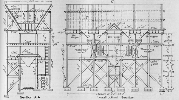
Some 2,000 tons of other metal work; 57,000 cu.yd. of excavation, and 215,000 cu.yd. of fill of different sorts completed the materials to be handled. Besides the walls, there had to be built 2,208 groined-arch panels and as many separate sections of floor slab and a total of 1,196 columns. This enumeration indicates the extent of the handling of forms. In brief the large tonnage to be fabricated into many units created a handling problem of exceptional magnitude. Plant Layout--A very satisfactory track arrangement, as shown by Fig. 8, was possible for bringing in materials and handling the spoil. With this important service arranged the disposition of the remaining units was tributary to the cableway which was selected as the main plant item, with the duty of handling all materials into the structure. As shown, the mixing plant was placed near one end with tracks leading from it along one side of the reservoir so that cars with buckets of concrete could run under the cableway span. The mixing plant arrangement and dimensions are given by Fig. 8. Aggregates are brought in by cars onto a trestle which parallels the plant on one side and are dumped through the trestle. Three bucket elevators feeding from hoppers under the trestle deliver the sand and crushed stone into the bins. These elevators have a capacity of 75 tons per hour each. On
the opposite side of the plant is a track for cement cars. These are unloaded into a cement house which is connected by a belt conveyor with the mixer charging floor. The cement elevator has capacity of 400 bags per hour. There are two 28-cu.ft. mixers each served from its own bin compartments and with its individual sand and stone measuring hoppers. Both mixers dump into a central hopper which feeds into the bottom-dump concrete buckets carried on cars. The bin hoppers, measuring
hoppers and receiving hopper, as shown by Fig. 8, are steel. In fact all the appliances of the plant are of excellent quality and the plant as a whole is remarkably well outfitted in a mechanical way, practically all operations being mechanical from the stockpiles to the concrete in the buckets on cars. Indeed, from the mixing plant the handling is all mechanical, by cars and then by cableway into the forms. Cableway Outfit--An 800-ft. span cableway on 85-ft. timber towers handles excavated material, concrete, reinforcing steel, forms, timber and workmen to or from any point within the rectangle of the reservoir structure. The main cable is 2 ˝ in. in diameter. For rock and earth large skips weighing about 16 tons loaded are employed. The concrete is handled in a 7-cu.yd. shear-gate bottom-dump bucket which weighs with its load about 15 to 16 tons. The cableway was designed for 15 tons load but it has on occasion carried 30 tons. A 300-hp. electric motor operates 52-in. hoisting and conveying drums through direct gears. As indicated in the view herewith towers are mounted on trucks and travel on tracks on either side of the reservoir. On each tower there is a 75-hp. motor geared directly to an elliptically-grooved drum which carries the steel haulage rope for moving the tower along the track. Both of these moving winches as well as the main hoist are controlled through magnetic controller-panel by one operator located on the head tower. In operation the loads are hoisted and conveyed at high speeds and at the same time both towers are moved along the trackways as desired. The speeds of travel of the towers are nominally 100 to 150 ft. per minute, but the speed attained in actual practice has seldom exceeded 100 ft. The nominal speeds of the cableway in conveying loads are up to 1,200 ft. per minute. Electric current for operating the cableway is taken off wires carried on a pole line parallel to the head-tower trackway. It is received at 2,200 volts and is
stepped down by a transformer on the head-tower to 440 volts. Near the top of each tower is a cross-arm which carries the conductor and control cables and the light and signal wires. These wires cross the work from tower to tower. From the light-wire high-power incandescent lights, with reflectors, are hung at frequent intervals. Drop wires for signals are also spaced at frequent intervals along the span so that it is easy to signal the operator from almost any part of the operation. As previously stated this cableway has handled practically all materials--spoil from the excavation, mixed concrete, reinforcing steel and forms--into, from and about the reservoir area. There is not a derrick or gin pole within the reservoir to supplement and cableway in distributing and placing materials. Concrete Construction--Three classes of concrete are used: (1) A 1:3:5 mixture, with 2 ˝ -in. stone, for the wall foundations, 16,500 cu.yd., (2) A 1:3:5 concrete, with 1 ˝ -in. stone, for walls, sub-floor and roof, 55,200 cu.yd., and (3) a 1:2:4 concrete, with 1-in. stone, for columns, floor and valve house and flume walls, 32,400 cu.yd. In placing the concrete, aside from the usual requirements of good practice, attention was given to the location of construction joints and continuity of placing. All walls were built above the footings in two lifts. In the outside walls the first lift went to elevation 211 which made the lower section 19 ft. 9 in. and the second section 18 ft. 3 in. high. In the dividing wall the
first lift went to the top of the spread base as indicated by Fig. 5. Along the walls there was an expansion joint every 60 ft. The walls therefore were concreted in sections 60 ft. long and one lift high, each unit as a single operation. The columns, however, were poured in one operation from footing to spring line. In the groined-arch roof construction joints were limited to the junction plane with the barrel arches and to vertical planes at mid-span. In the barrel arches construction joints were permitted only over expansion joints in the supporting
wall. The floor was poured in alternate sections of one panel are as previously described. Each unit within the joint limits indicated was invariably concreted as a monolith. All forms, except the steel forms for the circular columns, are make of wood in large units. The roof unit was a full groined-arch panel form about 20 ft. square. The cableway lifted the wood panel and shifted its position by means of a four-hook sling. For the walls the panels were made 45 ft. long and one-lift high. This required two panels for each 80-ft. section of wall but longer forms coming within any reasonable weight could not be made without being too limber. No unusual methods of bracing or fastening the wall forms were employed. The column forms had to be very firmly anchored to the footings to resist the lift due to the flare of the base section, but otherwise were connected and braced by usual methods. Progress in concreting has been rapid, from 12,000 to 18,000 cu.yd. a month having been placed during the season of 1922. Outstanding Construction Features--As a solution of a construction problem the operation at the Baldwin Reservoir in Cleveland is chiefly of interest in demonstrating the mobility of the long-span cableway. In this operation a rather ideal situation existed for cableway installation and operation--a rectangular construction area, with ample room for traveling towers on each of the long sides. With electrical control from the head tower, complete synchronism of travel of the two towers made the cableway a reasonable rapid means of transportation even when movement of the whole outfit was necessary. Its equal adaptability to loads of various kinds and forms combined with its mobility made it the sole transporting and hoisting device, besides the service railway, required on the work. Men in Charge--The reservoir was designed by and is being constructed under the supervision of the Frazier-Sheal Company, engineers, Cleveland, Ohio. Their resident engineer is H. T. Hammer. This work is being carried on by the Division of Water of the Department of Public Utilities of which A. B. Roberts is director, A. V. Ruggles, commissioner of water, and J. W. Ellms, consulting engineer on water purification. The contractor constructing the reservoir is the Stange-Walsh Construction Co., Cleveland, Ohio.
Cleveland Digital Library Webmaster Last updated March 7, 2003 This electronic, World Wide Web edition of the "Building the Baldwin Reservoir, Cleveland Water-Works," contains the complete text as found in the reprint of the original Engineering News-Record article from 1922. The site is hosted by the Cleveland State University Library and was prepared by civil engineering graduate student Callie Voiklis. © Website copyright 2003 by Cleveland State University. All rights reserved.
|