|
||||||
|
The Cuyahoga Valley Viaduct of the "Nickel Plate" Railroad By GEORGE H. TINKER, B.C.E. Bridge Engineer N.Y.C.& St. L. R.R. Read at the meeting of the Society October 13, 1908
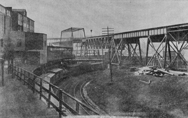
The Cuyahoga River flows through a deep and wide valley, in a tortuous channel with unstable clay banks. It forms the inner harbor of the City of Cleveland, and is crossed by many highways and railroads at various angles and different elevations. The New York, Chicago and St. Louis Railroad crosses the valley on a high steel viaduct, in a generally east and west direction, about one and a half miles from the lake. Several highways and railways, lying at different elevations are crossed in the length of the viaduct. At the east end the W. & L. E. R. R. is crossed, which in turn crosses the B. & O. R. R. and the river. A little farther on Canal Road and the B. & O. R. R. are crossed, the B. & O. R. R. also passing under Canal Road, so that the three lines of travel are superimposed one above the other and the railroad bridge above the highway bridge. Beyond the B. O. R. R. the viaduct passes over the Central Way freight house and tracks of the L. S. & M. S. R. R., and West 3rd St. Proceeding West the switching tracks of the Big Four Railroad to the lumber yards are crossed, and the Central Viaduct passes high overhead. The river is spanned by a drawbridge and immediately beyond are the main and yard tracks of the Erie R. R. and lastly University Road. The total length of steel structure is 3010.5 feet. It is double track throughout, the two tracks being 12 ft. 6 in. center to center. There are three curves upon the viaduct, one three degree and two four degree, the total length of curve being 951.1 feet and of straight track 2059.4 feet. There is an ascending grade to the west of 35/100 per hundred feet. The general elevation of the track above the valley is about 50 feet, and above the ordinary surface of water in the river seventy feet. When the end of the lift bridge is raised to its highest position it is over 260 feet above the bed of the stream below. The first structure, built at the beginning of the operation of the railroad, was a wrought iron viaduct, and consisted essentially of alternate tower and intermediate spans of the Fink pin-connected type. The various highways and railways were spanned by trusses of different lengths and types, and the river by a pin-connected deck swing span. The total weight of iron was 1661 tons. The substructure was sandstone masonry. The first train passed over the viaduct on August 26th, 1882. The Chief Engineer at that time was Mr. J. A. Latcha. Mr. W. M. Hughes was Bridge Engineer. The Engineer in charge of substructure was Mr. Wm. H. Boeh, and the present Secretary of the Cleveland Engineering Society staked out the foundations. The bridge was a good example of the state of the bridge builders' art at that time, and served its purpose well. The locomotives then in use on the road weighed 66 tons. Those in use today weigh 145 tons. With the increased weight of rolling stock weakness of details developed. An examination of the structure prior to its removal showed excessive wear on the pins on account of insufficient bearing area. Also the bracing was insufficient in the light of modern practice. These two defects caused a large amount of vibration and motion at the joints. The material itself was generally in excellent condition. The lower tower struts were an exception. Composed of two channels, they were so placed that one channel held water and dirt. In many cases the web was rusted entirely through. Another detail which showed excessive wear was the bearing of the floor beams on the top chords of the trusses. In many cases the flanges of the floor beams had cut through the cover plate of the chord. These facts, together with the desire to provide for an increase of load made it desirable to replace the wrought iron structure with one of steel designed for present day rolling stock. The new structure consists essentially of a plate girder viaduct, having alternate thirty-foot tower and sixty-foot intermediate spans. The typical structure is interrupted by the necessity for longer spans at various points, as was the original viaduct. Reconstruction was started on November 14th, 1904, at the crossing of Canal Road, and the B. & O. tracks. The original structure at this point consisted of skew spans having two deck trusses, and the skew was such that a panel point in one truss came opposite the end post in the other truss. When one track was loaded the deflection of the truss opposite the bearing of the other caused a high stress in the sway rods, which were continually breaking. In the new design four deck trusses are used, one under each rail, with the ties resting directly on the top chord. The span was made 125 ft. 9 in., spanning both highway and railroad. On account of limited headroom over Canal Road the depth of the trusses was made 20 feet. The connections are riveted and the pin-bearing shoes are placed under the top chord, in order to bring the bearing as near the rail as possible and avoid sway. Heavy rigid cross bracing is used at every panel point, and the two inside trusses are tied together at both top and bottom chords with a system of diagonal bracing in a horizontal plane. Top and bottom lateral bracing is used, so that the whole structure is very stiff and entirely free from vibration, but no vertical shear is transferred from one track to the other. The outside trusses are supported upon the column caps, and the inside trusses upon double-web cross girders riveted between the columns. The webs of these girders are 72 inches deep. The expansion ends of the trusses are seated on nests of seg- mental rollers. Hand riveting was employed upon this portion of the work. The weight of this span is 206 tons. In order to support the falsework over the B. & O. tracks four 60-foot plate girders which had been built for another job were borrowed and supported upon timber bents at each side of the tracks. Upon these were laid cross timbers and upon them the traveler tracks. To carry traffic during construction pony bents were erected on the level of the traveler run, supporting the stringers under one track. The other track was then abandoned, the old structure removed and the new erected for one track. Ties and rails were relaid and traffic resumed. The second track was then abandoned and the operation repeated. This, in general, was the method of procedure for the entire viaduct. Tower columns were lowered through the falsework and tied up close to their proper location. The track being supported upon the pony bents, and the old floor beams and trusses having been removed, the old columns were swung out and the new ones in, cross girders placed, and as much as possible of the tower bracing bolted up. Track girders could now be placed and the track relaid. The old masonry pedestals were found to be in good condition, and the length of spans was regulated so as to utilize them as far as possible. In some cases the capstone was removed and a new concrete cap placed. To accomplish this a concrete block of the proper dimensions was cast in a form erected by the side of the pedestal and at such an elevation that the block could readily be swung into place and bedded in cement mortar as soon as the old cap was removed. The new cap was then leveled and centered and the new column placed. The steel erection gang and the Company mason gang worked together in making such a change. After the column was set anchor bolt holes were drilled and anchor bolts grouted. After the completion of this first section, on February 21st, 1905, no further erection was done until the following spring. Work was then started at the east end and prosecuted continuously until the viaduct was completed. The use of the overhead traveler was abandoned and erection handled by means of two self-propelling derrick cars. A pneumatic riveting plant was also installed. From the east end to the section previously described the structure consists of the typical viaduct construction. The tower columns are built of Z-bar sections and have a batter of 1� inches per foot. The outside girders rest upon the column caps, and the inside girders upon a cross girder riveted between the column tops. The girders under each track are spaced 7 ft. 6 in. center to center, and the tracks are 12 ft. 6 ins. center to center. The 30-foot girders are fixed at both ends; the 60-foot girders have one fixed end and one sliding end. In order to simplify the details of the bearings the 30-foot girders are made the same depth as the 60-foot, viz.: 60 inches. The flanges of the 30-foot girders consist of two 5 x 3� x � inch angles and one cover plate 12 x � inch; those of the 60-foot girders of two 6 x 6 x 7/8 inches angles and three 15 inch cover plates, 5/8, 9/16 and 1/2 inches thick. Top and bottom flanges have the same section, but the first cover plate on the top flange is full length. Both 60-foot and 30-foot girders have stiff top and bottom laterals, end frames and intermediate cross frames made of angles. A special effort was made to get rivets enough in a connection to develop the full strength of the angle. Seven-eighths inch rivets were used throughout. The weight of four 30-foot girders and their bracing is 32,000 lbs., and of four 60-foot girders 100,000 lbs. The weight per foot of a single track girder span is given by the formula W = 10.5 L + 200, where L equals the length of the girder in feet. Cross ties are of oak and are 8 inches by 11 inches by 10 feet. They are spaced 14 inches center to center. The location of each tie was marked on the girder, the ties dapped and bored to fit over the rivet heads. The span over the Central Way freight house is a riveted through truss bridge with two trusses, 141 feet long. It is built on a slight skew with trusses spaced 29 feet center to center. The depth of the trusses is 30 feet center to center of chords. The weight of a double track floor beam is 14,000 lbs. The total weight of the span is 256 tons. In the erection of this span it was necessary to interfere with the working of the freight house as little as possible; therefore a special arrangement of false work was necessary. There are four house tracks on one side of the house and a team delivery platform on the other side. A bent was erected on the edge of the platform close to the tracks and another close to the house. Bents were placed between the tracks which were spread enough to allow cars to clear. Holes were cut through the roof of the house and bents lowered through. The floor was blocked up under the sills of these bents. The skew of this span is for the purpose of accommodating the tracks below; this also necessitated the use of a skew tower at the east end. The original construction at this point was rather unsightly because of the combination of skew and batter and the necessity for providing for the wider spacing of the trusses. In the new bridge this feature was avoided by the use of a special design of tower having four plumb posts. The columns in each bent are 29 feet center to center, and the two bents are 24 feet 7 inches center to center on one side of the tower and 33 feet 1 inch on the other side. The ends of the four track girders are supported on the cross girders, and the truss shoes on the column caps. Columns supporting the ends of trusses are of heavy section built up of plates and angles. The columns at the end of this span weigh 16,000 lbs. each. The west end of the span rests upon the old masonry pier on the line of West 3rd Street. The street is spanned by deck plate girders. The span is squared at the west end, making the girders of different lengths. The short girder is 82 feet 6 inches long, and the long girder is 88 feet 8 inches. The flange of the long girder is composed of two angles 6 x 6 x 7/8 inches and three cover plates 15 x 9/16 inches. The web is 108 inches deep at the center and 84 inches at the west end. The weight of the four girders and bracing is 92 tons. Beyond this point to the river the regular viaduct construction is continued except at the crossing of the Big Four tracks, where a 120-foot deck truss span is used, similar in design to the span over the B. & O. The weight of this span is 188 tons. At each end are three-bent towers. There are two curves on this part of the viaduct. The difference in length of inside and outside of curve is adjusted by varying the length of the intermediate girders; the tower girders being maintained at 30 feet. The elevation of the outer rail is secured by fastening blocks on the under side of the ties. During the erection of this portion of the viaduct a general strike of bridgemen occurred. Efforts were made to dynamite the bridge and several attempts made on the lives of the foreman and others. The work was conducted thereafter under the protection of armed guards. We have now arrived at the point where trouble begins, viz: at the bank of the Cuyahoga River. The preliminary studies of
the situation at this point contemplated the erection of a swing span upon the old center pier. During the year 1905 plans were drawn for reinforcing the old pier to carry a longer and heavier span. Borings were made in the river bottom to determine the character of the foundation. Holes over 100 feet deep showed mud and clay becoming gradually harder from forty feet down. It was decided that a safe bearing of ten tons per pile could be secured, and upon this basis plans were drawn for a swing span 80 feet longer that the old span, which would provide a 120-foot channel each side of the center pier. The new trusses would have been erected outside of the old trusses upon a new drum outside of the old drum, the whole stayed together temporarily and swinging together, thereby maintaining traffic on the river and on the railroad and accomplished the erection of the new span without falsework. When the new steel reached the end of the old temporary bearings would be provided and the live load thereafter carried by the new trusses. The old span would then be removed from within the new and the new machinery installed. In the meantime the 40-foot extension on each end would be erected on shore and spliced to the swinging portion simultaneously at both ends, the temporary bearings removed and the permanent ones put into service. This scheme was the subject of careful study for upwards of a year and seemed to be a satisfactory solution of the problem. Approval of the plans was obtained from the City of Cleveland the State of Ohio, and the U.S. War Department. Bids were received and contracts let when objection was raised to maintaining the center pier, and the city withdrew its approval. It was then decided to erect a Scherzer rolling lift bridge, placing the free end on the old West river pier, and the rolling end upon a tower standing just east of the old center pier. In May, 1906, work was begun upon the foundations for the lift pier. A double row of sheet piling was driven enclosing the site, and the space between filled with clay. The construction of this cofferdam was a very difficult piece of work. The soft mud of the bottom afforded a poor hold for the piles, and notwithstanding the sides of the cofferdam were strongly braced with 16-inch timbers, they bulged badly and it was with great difficulty that the water was kept out. On the 6th of December the cofferdam was at last completed and the pit emptied. On the 18th the driving of foundation piles was begun. Excavation and pile driving were carried on simultaneously in different parts of the pit. On the 4th of January, 1907, the pit was flooded by high water. At 4:00 P.M. on the 6th the pumps were started and the pit emptied at 3:00 A.M. the next day. Two feet of silt had been deposited. On the 9th excavation was again in progress, and nine days later the first concrete was deposited. There had been 1448 cubic yards of mud excavated from the pit. As the level of the concrete was raised the timber bracing was removed. Concrete was conveyed to place by chutes from two mixers. The proportion of ingredients was one barrel of cement to 10� cubic feet of sand and 27 cubic feet of broken stone, making one cubic yard of concrete. The mixture was wet, and salt was added in freezing weather, which was most of the time. Fires were kept burning at night and none of the concrete froze. The lift pier consists of four pedestals upon a common slab footing, and connected together by four walls ten feet wide on top and thirteen feet deep. These walls are reinforced with eye-bars taken from the old bridge. In order to accommodate the skew of the channel the upstream corner on the channel side was cut off and the pier extended upstream on that corner to secure a larger number of piles and equalize the bearing on the foundation. There are 782 piles in the foundation; 204 are under the pedestal carrying the southwest leg of the tower. They are driven to a depth of 35 feet below the bottom of the excavation. The penetration under the last blow of a 3200lb. hammer, fall-
ing 38 feet, was about 2� inches. The average safe load per pile, computed by the Engineering News formula, is 25 tons. The maximum load that can come on the 204 piles under this corner is 9.85 tons per pile. If there should be any tendency towards unequal settlement, the tie walls, acting as cantilevers, with the rods strained at 16,000 lbs. per square inch will transfer 17 percent of the load to the adjacent corners of the pier. So far as can be determined after the expiration of a year there has been no settlement whatever. The pedestals are 10 x 15 feet at the top and about 11 feet out of water. Long anchor bolts were built into them for securing the base of the columns. There are 2974 cubic yards of concrete in the pier and its weight in air would be 6,000 tons. As soon as the pile driver force could be released it was moved across the river and started upon the foundations for the west pier. The conditions were different here, in that the old masonry pier had to be removed and a new concrete pier built in the same place. It has been mentioned that the banks of the Cuyahoga River are unstable. In years past the old pier had moved towards the channel, an experience not unique with the Nickel Plate, and the pier cracked in places, so that it was considered advisable to rebuild it on a deeper foundation. Falsework bents were driven in front and in rear of the pier, and while driving the latter on April 4th the pier commenced to break up and showed signs of collapsing. The top of the pier was removed and some old floor beams placed across the caps of the falsework bents to carry the end of the draw and the fixed span to the west. The work of demolishing the old pier was then continued, while the driving of the cofferdam was in progress. Driving was greatly interfered with by the presence of old piles or snags in the river. On the 22nd of April the old pier was all removed and on the 16th of the next month the sheet piling was driven. The cofferdam was filled with a mixture of 1� parts of clay and one part of gravel, with some straw and hay. Some material was also dumped outside the cofferdam. On the 3rd of June a vessel going upstream was unable to make headway against the current and stuck with her stern opposite the cofferdam for several hours. The current set up by her propeller in the violent efforts made to extricate herself scoured the channel to a depth of 28 feet. When the pumps were started the next morning the dam leaked badly. The leak was stopped by a mixture of clay and fine manure. As the water was lowered in the pit leaks developed from time to time, but could always be stopped by the use of the clay and manure mixture. Vessels struck the protection piling outside the cofferdam frequently, breaking the bracing and causing a great deal of damage. On one occasion a falsework bent was knocked out of plumb and the men hastily left the work for fear the whole bridge would fall into the pit. It was noticeable that certain pilots always hit the protection and others never did. During this month excavation was in progress, and in July the foundation piles were driven. There are 155 piles, about the same length as on the other side of the river. The driver leads had to be shortened in order to get under the falsework, so that the fall of the hammer at the last blow was 25 feet; with a 3200 lb. hammer, the penetration was 1� inches. The average safe load per pile, figured as before, is 34 tons. There were 669 cubic yards of material excavated. Concreting began on August 4th. The pier is of rectangular form, but having the downstream corner on the channel side cut off slightly. There are 1,444 cubic feet of concrete, and a number of old eyebars and rods are embedded, both horizontally and vertically. On account of the falsework and the old draw the pier could not be finished to the level of the bridge seat. Two large blocks of concrete to carry the bearing of the lift and adjacent span were therefore cast and conveniently placed where they could be picked up and swung into position by a derrick car when the
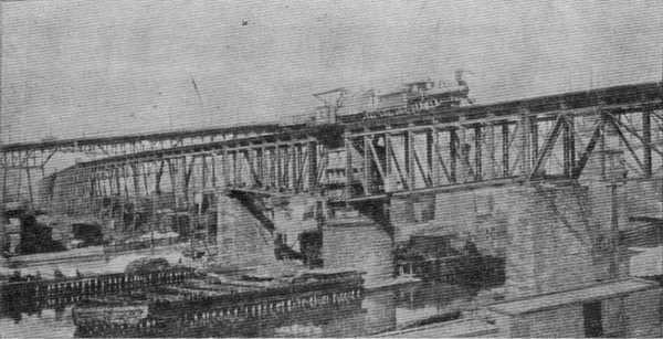
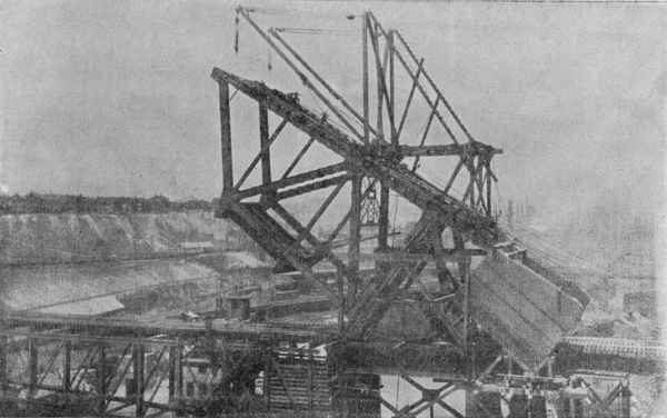
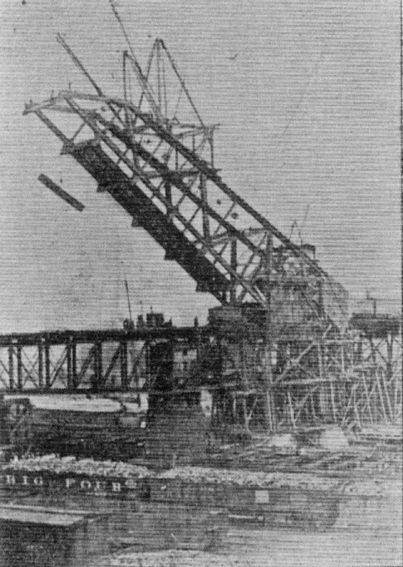
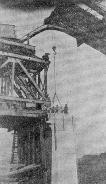
change should be made. Forms were then built for the top of the pier and the blocks concreted in. This method of completing a pier has been adopted several times and permits a satisfactory job. On the 30th of April four panels were cut off the end of the old swing and a sand box built into the shortened arm to act as a counterweight. The lift tower could now be erected without interfering with the swinging of the draw. The tower consists of four heavy columns capped by two double-web girders, which carry the tracks upon which roll the segmental girders. The lift was erected in the raised position, at an angle of about 35 degrees. The first floor beam and panel of stringers were omitted, permitting trains to pass through. As soon as the trusses were erected as high as the derrick car could reach a long-and-short legged traveler was erected upon the top chord, and moved up the chord as the erection progressed. The seg- mental girders were kept blocked, and counterweight was added from time to time to keep the span balanced. The alignment of the trusses was regulated during erection by the use of a transit, so that when the lift was lowered to a bearing on the rest pier there was no troublesome error to correct. The motive power is electricity, applied through two 52 H.P. alternating motors, 60 cycles, 3 phase, running at 560 revolutions per minute, and using current at 440 volts. Only one motor is used at a time, the other being held as a reserve. The motors are mounted upon a machinery deck, above the track and move with the bridge. The operating house is supported upon brackets at the side of the tower. Besides the switch board, controllers and indicators the house contains a gasoline engine for auxiliary or emergency use. Motion is transmitted through gearing and shafts to the main driving pinion on the machinery deck. As the machinery deck moves and the engine is fixed the difference in the relative position of the two is accommodated by an arrangement of shafts and gears which allows a shaft to slide through one pinion as the distance between the pinion at each end varies. The operation of the bridge by either power is perfect. The time of operation, to open or close is about 1� minutes by electric motor and 14 minutes by gasoline motor. There are solenoid brakes on the motors and a band brake in the operation house for use with the gasoline engine. With these brakes all off the bridge will stand at any angle. The ties and rails were fastened upon the lift, except the first panel, before it was lowered into position. The machinery was put into commission and the bridge operated as far as possible to see that everything was in smooth working condition. The length of the span is 162.5 feet and the clear channel between protection piling is 120 feet. The weight of the movable span is 521 tons. The counterweight is 638 tons of which 90 tons are pig iron and 548 tons are concrete. The weight of the tower is 348 tons. While the river portion was being erected the three spans west of the river were also under way so that the final connection was made at the west river pier. The span next west of the river is a 120-foot deck truss span with four trusses, essentially similar to the 125-foot span previously described. Its weight is 228 tons. It was erected on falsework in the usual manner. West of this is a 120-foot through riveted span with two trusses spaced 30 feet center to center. The trusses are 30 feet deep. The span is upon a curve and the elevation of the outer rail is accomplished by framing the stringers at different elevations. Both of these spans are over tracks of the Erie Railroad, and are supported upon the original masonry piers except at the west river pier. The weight of the through span is 231 tons. The west span of the bridge is a 103-foot through plate girder span over University Road. There are two girders with 120 inch webs, spaced 30 feet 6 inches center to center. The flanges are composed of two angles 8 x 8 x 7/8 inches; two side plates 16 x 11/16 inches and four cover plates 22 x 3/4 inches. The girders have pin-bearing shoes. The floor beams are of built I section and have large gussets riveted to stiffener angles on the web of the girder. The stringers are rolled I beams, and are framed at different elevations as in the previous span. The end stringers of both through span and through girders are carried at their shore ends on stringer struts, and these struts have bearings on the bridge seat under the end of each stringer. The weight of the girder span is 211 tons. Each girder was shipped riveted up and erected by means of gallows frames at each end.
On the morning of October 19th, 1907, the old draw was swung for the last time. As this was 25 years and 6 weeks since the first train passed over, it was clearly entitled to membership in the Nickel Plate Veterans' Association. Falsework had previously been erected on the protection pier to receive the old draw, and the work of dismantling immediately begun. Traffic was abandoned for the first time during the reconstruction of the bridge. A derrick car was run out to the end of the deck span and the concrete blocks for the bridge seat previously mentioned hoisted and bedded in position on the pier. These blocks are at the level of the lower chord of the deck span, and the masonry of the pier stops at this point. To receive the bearings of the free end of the lift, which are at the level of top chord of the deck span, massive steel columns were built, forming a bent on the pier and weighing 18,000 lbs. each. In the attempt to place the first of these a distressing accident occurred, which marred the completion of the work and tuned a day of great satisfaction into one of gloom and sorrow. The overturning of a derrick car, when about to lower a column, resulted in the death of three men, J. S. Yates , the foreman in charge of the erection; F. T. Diehl, trainmaster, and a watchman. Mr. Yates was well known as a bridge erector of more than ordinary ability. He had erected many of the new bridges on the Nickel Plate, and had been in active charge of the erection of the Cuyahoga Valley viaduct from the start of reconstruction. This was perhaps his
largest single piece of work, and it is one of the ironies of fate that the day that was to have seen the last link erected should have been his last upon earth. This accident delayed the erecting of this connecting portion until the next day, the 11th of October, 1907, upon which day the first train passed over the new structure. The weight of the completed structure is 4,913 tons, three times the weight of the old, and it had taken practically three years to reconstruct. During all this time, except about 36 hours, while changing the draw, traffic had been maintained continuously. The specifications under which the viaduct was built call for a load on each track of two 136-ton locomotives followed by a uniform load of 4,000 lbs. per foot. The steel used is of the grade known as structural steel, having an ultimate strength of 56,000 to 64,000 lbs. Rivets are of a softer grade, known as rivet steel, having an ultimate strength of 46,000 to 54,000 lbs. The unit stress used is 7500 lbs. per square inch, modified by the proportion (1 + Min./Max.). The minimum thickness of material is 3/8 inch, except for fillers and lacing bars. Cast steel is used only in machinery parts, shoes and pedestals being built of rolled steel. No cast iron is used. The appearance of the structure is massive. The distinctive features are stiff riveted members, stiff bracing and full riveted connections. The entire superstructure was manufactured by the King Bridge Company of Cleveland, of which Mr. Harry Fuller is Chief Engineer, and to his skill and attention to details is due, in large part, the satisfactory character of the structure. The erection was handled by the Pittsburg Construction Company. To their careful management is due the freedom from interference with traffic, the successful conduct of the work, and the excellent character of the workmanship. Mr. A. J. Himes was Bridge Engineer of the Railroad during the planning and design of the work. The substructure work was done by the Company forces, under Mr. E. E. Hart, Chief Engineer. The writer's connection with the work began with the erection of the first portion, and a large part of his attention thereafter was occupied by the inspection of the material and workmanship, and the oversight of the erection.
Cleveland Digital Library Webmaster Last updated March 7, 2003 This electronic, World Wide Web edition of the "The Cuyahoga Valley Viaduct of the "Nickel Plate" Railroad," by George H. Tinker, contains the complete text as found in the reprint of the original Transactions, The Cleveland Engineering Society article from 1908. The site is hosted by the Cleveland State University Library and was prepared by civil engineering graduate student Callie Voiklis. © Website copyright 2003 by Cleveland State University. All rights reserved.
|